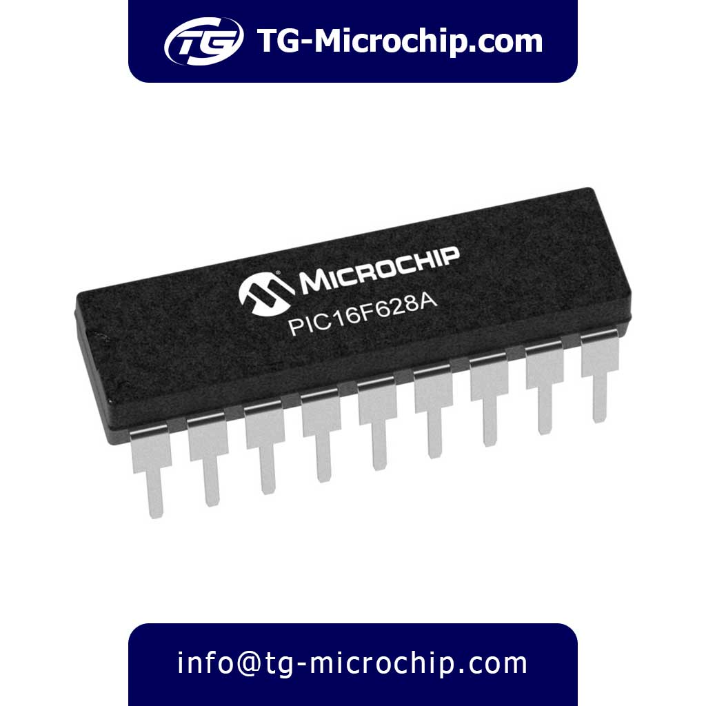
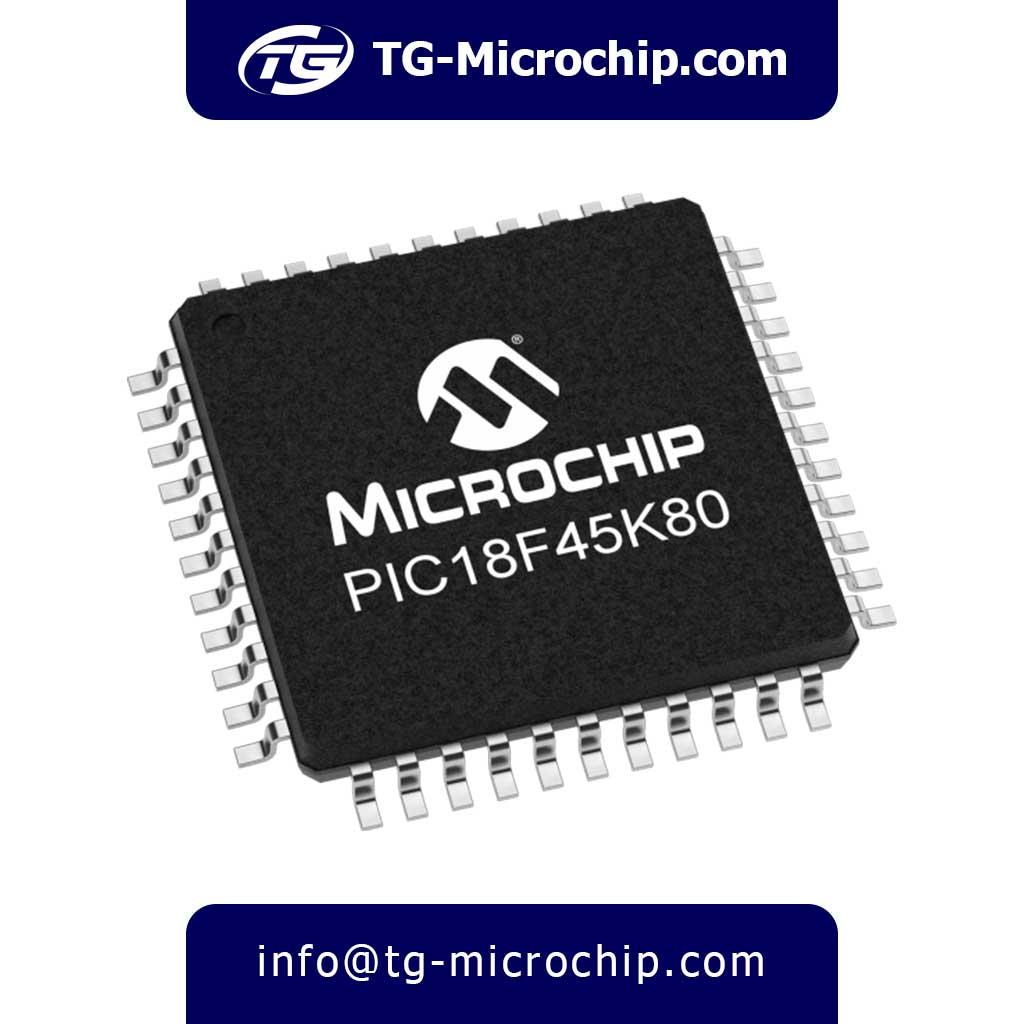
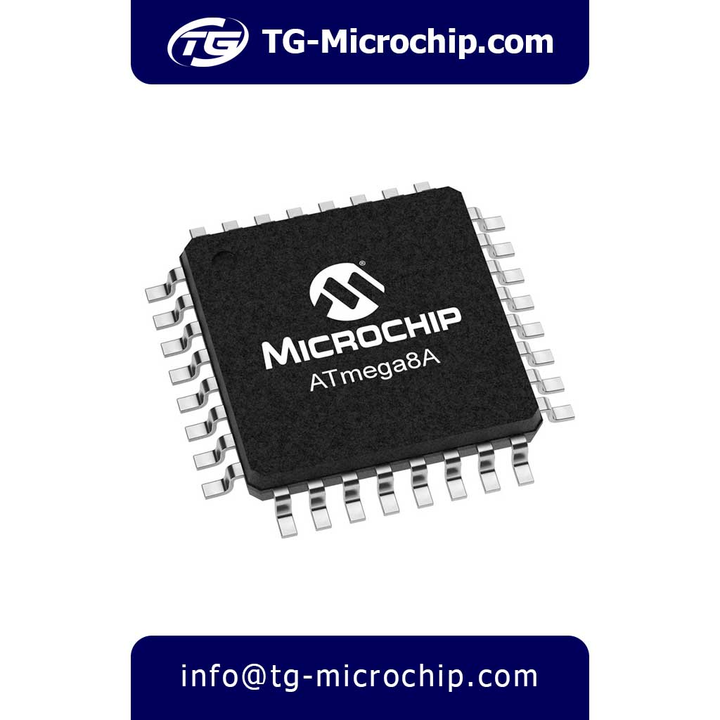
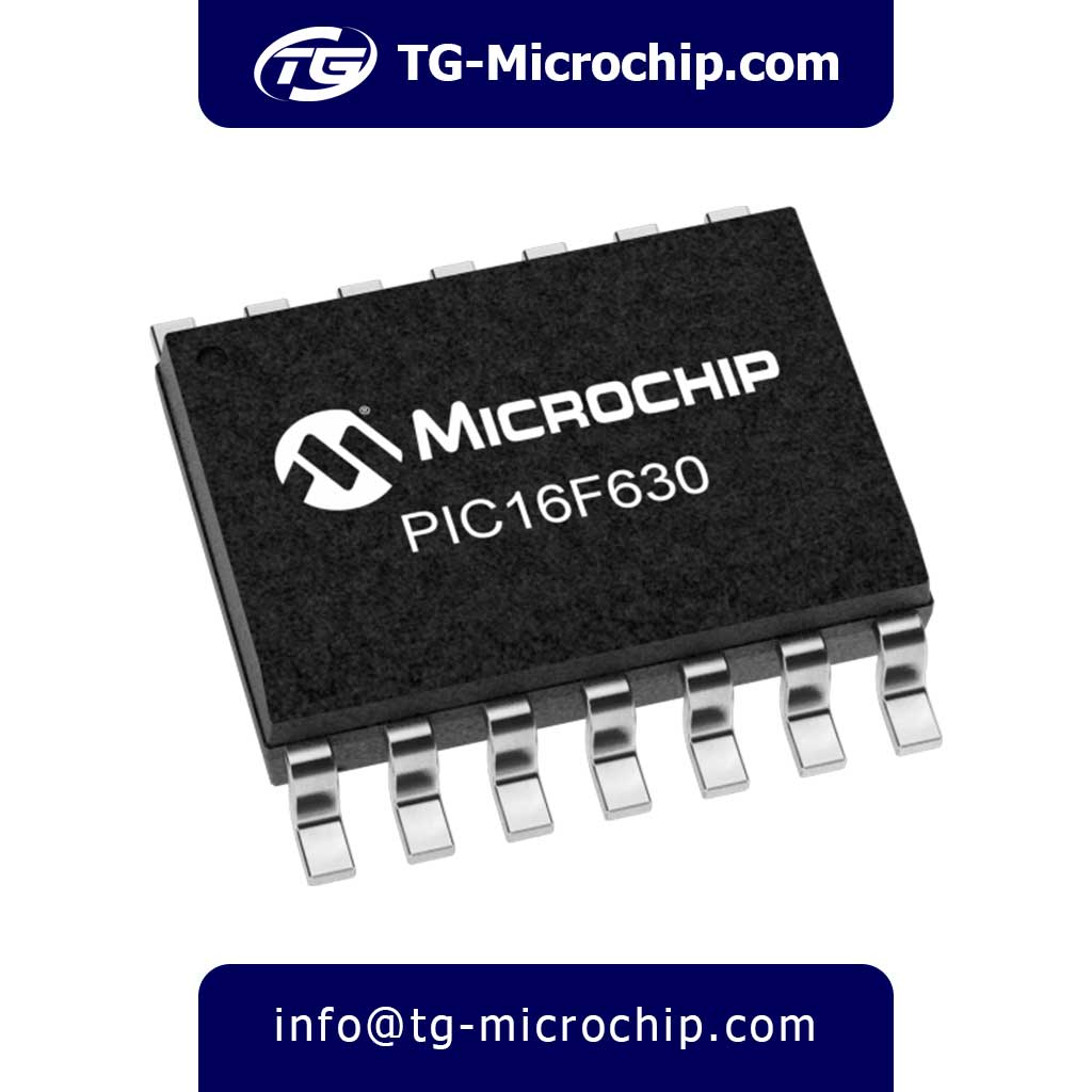
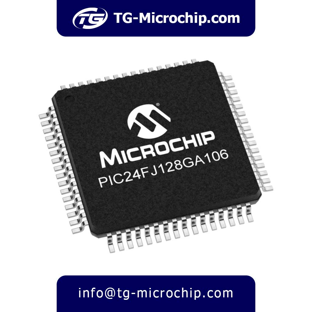
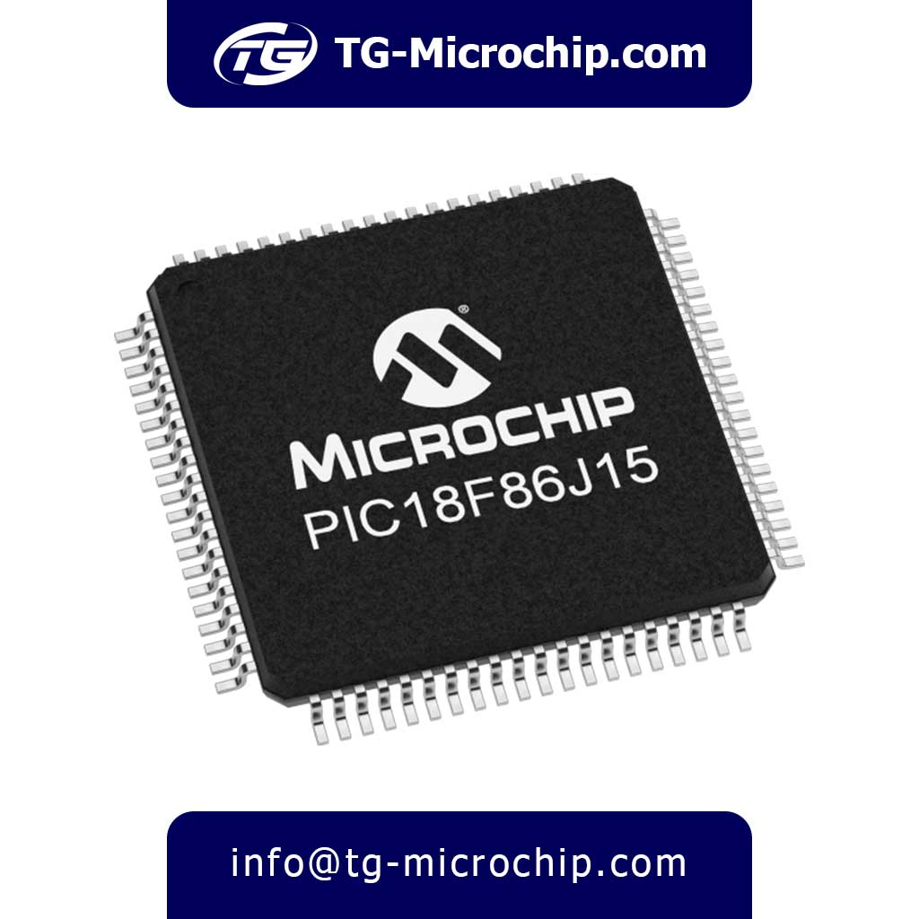
For order or price inquiry of PIC16F628A-I/P Microchip Technology / Atmel – 8-bit Microcontroller – MCU, Please click on Buy Order button and fill the RFQ form we will check out inventory and offer you our best price .
Quick Access
About
The PIC16F628A-I/P is an 8-bit microcontroller from Microchip Technology, designed for embedded control applications. It features a Harvard architecture with a RISC-based core, enabling efficient execution of instructions at clock speeds up to 20 MHz. With 3.5 KB of Flash program memory, 224 bytes of SRAM, and 128 bytes of EEPROM, it offers a balanced mix of storage and performance for small to medium-complexity projects. The microcontroller operates across a wide voltage range (3V to 5.5V), making it suitable for both battery-powered and line-powered systems.
A key strength of the PIC16F628A-I/P is its versatile peripheral set, which includes two 8-bit timers, one 16-bit timer, and two analog comparators. While it lacks an ADC (Analog-to-Digital Converter), it compensates with a USART (Universal Synchronous Asynchronous Receiver Transmitter) for serial communication, making it ideal for applications requiring UART connectivity. Additionally, it supports in-circuit serial programming (ICSP), allowing for easy firmware updates without removing the chip from the circuit.
The microcontroller comes in an 18-pin PDIP (Plastic Dual In-Line Package), which is widely used in prototyping and through-hole PCB designs. Its industrial-grade operating temperature range (-40°C to +85°C) ensures reliability in harsh environments, including automotive and industrial control systems. The PIC16F628A-I/P also includes built-in features like Power-on Reset (POR), Brown-out Reset (BOR), and a Watchdog Timer (WDT) for enhanced system stability.
Compared to similar models like the PIC16F627A-I/P, the PIC16F628A-I/P offers double the Flash memory (3.5 KB vs. 1.75 KB), while maintaining the same RAM and EEPROM capacities. However, it lacks some advanced features found in newer microcontrollers, such as SPI/I²C interfaces or PWM modules, which may limit its use in more complex applications. Despite this, its simplicity, ease of use, and robust design make it a popular choice for hobbyists and engineers alike.
Typical applications for the PIC16F628A-I/P include industrial automation, consumer electronics, sensor interfacing, and basic control systems. Its combination of low power consumption, sufficient memory, and essential peripherals makes it well-suited for cost-sensitive projects where advanced features are not required. Overall, the PIC16F628A-I/P remains a reliable and widely used microcontroller in the embedded systems landscape.
Features
Core Architecture:
- 8-bit RISC CPU with modified Harvard architecture
- 35 single-word instructions (14-bit wide)
- 2-level deep hardware stack
- 8-bit ALU with hardware multiplier
- Direct, indirect and relative addressing modes
- 2-stage instruction pipeline (fetch and execute)
Clock System:
- DC to 20MHz operating frequency
- 4 clock modes selectable via configuration bits:
- LP (Low Power Crystal) – 32kHz to 200kHz
- XT (Crystal) – 200kHz to 4MHz
- HS (High Speed Crystal) – 4MHz to 20MHz
- RC (Resistor-Capacitor) – variable frequency
- Internal 4MHz oscillator with software tunable output
- Clock switching capability during operation
- Fail-Safe Clock Monitor (FSCM)
- Two-Speed Start-up mode
Memory Organization:
- 3.5KB (2048 x 14) Flash program memory
- 224 bytes general purpose SRAM
- 128 bytes EEPROM data memory
- 8-level deep hardware call stack
- Memory partitioning:
- Program memory divided into 2 pages
- Data memory organized in 4 banks
- Special Function Registers (SFRs)
- General Purpose Registers (GPRs)
I/O Ports:
- 16 programmable I/O pins (of 18 total pins)
- PORT A: 6 bidirectional I/O pins (RA0-RA5)
- PORT B: 8 bidirectional I/O pins (RB0-RB7)
- Individual direction control for each pin
- High current sink/source (25mA max per pin)
- Weak pull-ups on PORTB (software controllable)
- Schmitt trigger inputs on all digital I/O
- Open-drain capability on PORTB
Interrupt System:
- 12 interrupt sources including:
- Timer0 overflow
- Timer1 overflow
- Timer2 match
- PORTB change
- Comparator output change
- USART transmit/receive
- EEPROM write complete
- Priority-based interrupt handling
- Context saving during interrupts
Timers:
- Timer0:
- 8-bit timer/counter
- 8-bit programmable prescaler
- External clock input option
- Interrupt on overflow
- Timer1:
- 16-bit timer/counter
- Prescaler (1,2,4,8)
- Gate control mode
- External clock input
- Synchronous/asynchronous operation
- Timer2:
- 8-bit timer with period register
- 4-bit prescaler
- 4-bit postscaler
- PWM time base capability
Analog Features:
- Two analog comparators with:
- Programmable reference voltage
- Hysteresis control
- Output polarity control
- Interrupt capability
- External output option
Communication Interfaces:
- USART module with:
- Full-duplex asynchronous mode
- Half-duplex synchronous mode
- 9-bit address detection
- Framing error detection
- Automatic baud rate detection
- Baud rate generator
Power Management:
- Operating voltage: 3.0V to 5.5V
- Low power consumption:
- < 2mA @ 5V, 4MHz
- < 20μA @ 3V, 32kHz
- < 1μA in Sleep mode
- Multiple power-saving modes:
- Idle mode
- Sleep mode
- Peripheral disable modes
Special Features:
- In-Circuit Serial Programming (ICSP)
- In-Circuit Debugging (ICD) support
- Watchdog Timer with:
- Dedicated RC oscillator
- Programmable period (1ms to 268s)
- Windowed operation mode
- Brown-out Reset (BOR)
- Power-on Reset (POR)
- Power-up Timer (PWRT)
- Oscillator Start-up Timer (OST)
Protection Features:
- Flash/EEPROM write protection
- Code protection bits
- Configuration bits protection
- User ID locations (4 x 14-bit)
- Device ID registers
- Checksum calculation
Package Characteristics:
- 18-pin Plastic DIP (PDIP)
- Lead pitch: 2.54mm (0.1″)
- Package dimensions: 22.86mm x 6.35mm
- Operating temperature: -40°C to +85°C
- Storage temperature: -65°C to +150°C
- ESD protection > 4kV on all pins
Development Support:
- MPLAB IDE compatible
- Full debugger support
- Third-party tool support
- Extensive application notes
- Reference designs available
- Hardware/software libraries
Advantages
1. Cost-Effectiveness and Accessibility
- Budget-friendly solution for basic embedded control applications
- Widely available in the market with multiple sourcing options
- Low total system cost due to minimal external component requirements
- Proven legacy design with extensive documentation and community support
- Easy to prototype with through-hole DIP package for breadboard testing
2. Power Efficiency and Flexible Power Management
- Ultra-low power consumption extends battery life in portable applications
- Wide operating voltage range (3V-5.5V) accommodates various power sources
- Multiple power-saving modes including Sleep mode (<1μA) for energy-critical designs
- Dynamic clock switching allows runtime optimization of power vs performance
- Brown-out Reset protection maintains reliable operation during power fluctuations
3. Robust Performance and Reliability
- Industrial temperature range (-40°C to +85°C) ensures operation in harsh environments
- Proven RISC architecture delivers deterministic real-time performance
- Built-in Watchdog Timer prevents system lock-ups in critical applications
- Excellent noise immunity through robust I/O port design
- Long-term availability as part of Microchip’s mature product portfolio
4. Development and Programming Advantages
- In-Circuit Serial Programming (ICSP) enables easy field updates
- Extensive development tool support including MPLAB X IDE
- Large code base and examples from decades of use in the industry
- Shallow learning curve for engineers familiar with PIC architecture
- Reusable code across similar PIC16F family members
5. Application-Specific Benefits
- Excellent for control-oriented applications with its timer-rich architecture
- Ideal for basic communication tasks with built-in USART module
- Strong in low-speed analog applications with dual comparators
- Perfect for cost-sensitive designs requiring non-volatile storage (Flash+EEPROM)
- Great educational tool for learning embedded systems fundamentals
6. Maintenance and Longevity Advantages
- Flash memory allows unlimited firmware updates during development
- EEPROM retention maintains calibration data through power cycles
- Proven silicon reliability with decades of field experience
- Backward compatible with earlier PIC16F62x designs
- Scalable to more advanced PICs when project requirements grow
7. Integration Benefits
- Reduces component count by integrating timers, comparators and memory
- Eliminates need for external EEPROM in many applications
- Minimizes board space compared to discrete solutions
- Simplifies BOM management with single-chip solution
- Reduces EMI issues versus multi-chip implementations
8. Time-to-Market Advantages
- Rapid prototyping possible with readily available evaluation tools
- Short design cycles due to mature architecture
- Abundance of reference designs for common applications
- Predictable performance from well-characterized silicon
- Reduced certification effort for products upgrading from previous versions
Applications
1. Industrial Automation & Control Systems
- Motor Control: Used in small DC/stepper motor controllers for conveyor belts, robotic arms, and CNC machines due to its PWM and timer modules.
- Sensor Interfacing: Processes signals from temperature, pressure, or proximity sensors via its analog comparators, ideal for factory monitoring systems.
- PLC Replacements: Acts as a low-cost alternative for programmable logic controllers (PLCs) in simple automation tasks like sequencing or relay control.
2. Consumer Electronics
- Home Appliances: Embedded in washing machines, microwaves, and air conditioners for button debouncing, mode selection, and timing functions.
- LED Lighting Control: Drives LED matrices or strips using direct I/O control and PWM (software-implemented) for dimming effects.
- Remote Controls: Powers IR-based remotes with its low-power Sleep mode (2µA standby current) and wake-on-interrupt capability.
3. Automotive & Transportation
- Dashboard Displays: Manages odometer readings or fuel gauges via its USART module for communication with other ICs.
- Basic ECU Functions: Controls fuel injectors or ignition timing in low-end vehicles using timer-based triggers.
- Battery Management: Monitors voltage thresholds in electric scooters or auxiliary systems using comparators and brown-out reset.
4. Embedded Hobbyist & Educational Projects
- DIY Robotics: Serves as the brain for small robots with servo motor control and obstacle detection (via comparators).
- Data Loggers: Stores environmental data (e.g., temperature) in its 128-byte EEPROM for portable sensors.
- Prototyping: Popular in breadboard projects due to its DIP-18 package and ease of programming with ICSP.
5. Medical & Laboratory Devices
- Portable Monitors: Powers glucose meters or pulse oximeters with low-voltage operation (3V–5.5V) and compact design.
- Lab Equipment: Controls stirrers or centrifuges with precise timer-based operation.
6. Communication & Peripheral Interfaces
- Serial Adapters: Converts UART signals (e.g., RS-232) for PC-to-microcontroller communication.
- Custom Keyboards: Interfaces with mechanical switches for bespoke input devices.
7. Security & Safety Systems
- Alarm Systems: Triggers sirens or lights based on door/window sensor inputs (using interrupt-on-change).
- Fire Detectors: Processes signals from smoke sensors via comparators and initiates alerts.
Key Strengths for These Applications
- Cost-Effective: Low BOM cost for high-volume production.
- Rugged Design: Industrial temperature range (-40°C to +85°C) suits harsh environments.
- Legacy Support: Backward compatibility with older PIC16F designs simplifies upgrades.
Specifications
| Category | Specification |
|---|---|
| Manufacturer | Microchip Technology |
| Product Category | 8-bit Microcontrollers (MCU) |
| Product Type | Microcontroller (MCU) |
| Series | PIC® 16F |
| Part Number | PIC16F628A-I/P |
| Package / Case | PDIP-18 (18-Pin Plastic Dual In-Line Package) |
| Mounting Type | Through-Hole (THT) |
| Core Processor | PIC (8-bit Harvard architecture, RISC-based) |
| Core Size | 8-bit |
| Clock Speed (Max) | 20 MHz |
| Program Memory Size | 3.5 KB (2048 x 14-bit Flash) |
| RAM Size | 224 bytes (SRAM) |
| EEPROM Size | 128 bytes |
| Operating Voltage | 3V to 5.5V (Wide voltage range) |
| Number of I/O Pins | 16 (of 18 total pins) |
| Digital I/O | 16 (TTL/CMOS compatible) |
| Analog Inputs | None (No ADC, but has 2 analog comparators) |
| Timers | – 2 x 8-bit (Timer0, Timer2) – 1 x 16-bit (Timer1 with gate control) |
| Comparators | 2 (Analog comparators with programmable reference) |
| Communication Interfaces | UART (USART) (No SPI or I²C built-in) |
| PWM Channels | None (No dedicated PWM, but can be implemented via software) |
| Oscillator Type | Internal (4 MHz with PLL support) or External (up to 20 MHz) |
| Operating Temperature | -40°C to +85°C (Industrial grade) |
| Special Features | – Brown-out Reset (BOR) – Power-on Reset (POR) – Watchdog Timer (WDT) – In-Circuit Serial Programming (ICSP) |
| Terminal Pitch | 2.54 mm (standard DIP spacing) |
| Data Retention | > 40 years (Flash memory) |
| Write/Erase Cycles | 100,000 (Flash), 1,000,000 (EEPROM) |
Comparison with Similar Components
1. Core Architecture Comparison
PIC16F628A-I/P
- 8-bit RISC core with 35 instructions
- 2-stage pipeline (fetch/execute)
- 8-bit ALU with hardware multiplier
- 8-level hardware stack
Comparable Devices:
- PIC16F627A-I/P: Identical core architecture
- PIC16F648A-I/P: Adds deeper 16-level stack
- PIC16F1829-I/P: Enhanced mid-range core with 49 instructions
- PIC16F84A-20/P: Legacy architecture with single-level stack
Analysis:
The 628A’s core represents Microchip’s mature baseline 8-bit architecture. While newer devices like the 1829 offer enhanced instruction sets, the 628A provides sufficient performance for most control applications. The 8-level stack limits complex subroutine nesting compared to the 648A’s 16-level implementation.
2. Memory Subsystem Breakdown
PIC16F628A-I/P
- 3.5KB (2048 x 14) Flash
- 224B RAM
- 128B EEPROM
- 10,000 Flash write cycles
- 1M EEPROM write cycles
Memory Comparison Table:
| Part Number | Flash | RAM | EEPROM | Flash Endurance | EEPROM Endurance |
|---|---|---|---|---|---|
| PIC16F627A-I/P | 1.75KB | 224B | 128B | 10K | 1M |
| PIC16F648A-I/P | 7KB | 256B | 256B | 10K | 1M |
| PIC16F684-I/P | 3.5KB | 128B | 256B | 10K | 1M |
| PIC16F1829-I/P | 14KB | 1KB | 256B | 10K | 1M |
Key Observations:
- The 628A offers a balanced memory configuration for medium-complexity firmware
- 648A doubles Flash/EEPROM capacity for data-intensive applications
- 1829 provides substantial RAM expansion for data processing tasks
3. Digital I/O Capability Analysis
PIC16F628A-I/P I/O Features:
- 16 bidirectional I/O pins
- 25mA sink/source per pin
- Weak pull-ups on PORTB
- Interrupt-on-change
- Schmitt trigger inputs
I/O Comparison:
| Part Number | Total Pins | I/O Pins | Max Current | Special Features |
|---|---|---|---|---|
| PIC16F684-I/P | 14 | 12 | 25mA | Analog input capability |
| PIC16F1829-I/P | 20 | 18 | 25mA | Configurable logic cells |
| PIC16F84A-20/P | 18 | 13 | 25mA | None |
Critical Notes:
- 628A’s 16 I/O pins provide excellent connectivity in 18-pin package
- 1829 offers pin remapping and configurable logic for complex interfaces
- 684’s reduced pin count limits larger designs
4. Analog Performance Evaluation
PIC16F628A-I/P Analog Features:
- 2 analog comparators
- Programmable reference voltage
- No ADC peripheral
Analog Capabilities Comparison:
| Part Number | ADC Resolution | ADC Channels | Comparators | Special Analog Features |
|---|---|---|---|---|
| PIC16F684-I/P | 10-bit | 8 | 2 | ADC with auto-acquisition |
| PIC16F88-I/P | 10-bit | 7 | 1 | ADC with temperature sensor |
| PIC16F1829-I/P | 10-bit | 12 | 2 | ADC with computation accelerator |
Design Implications:
- 628A requires external ADC for sensor applications
- 684 provides best analog integration in small package
- 1829 offers most advanced analog processing
5. Communication Interface Showdown
PIC16F628A-I/P Communication:
- USART (asynchronous only)
- No SPI/I2C hardware
Communication Peripheral Comparison:
| Part Number | USART | SPI | I2C | Special Comm Features |
|---|---|---|---|---|
| PIC16F87-I/P | AUSART | Yes | Yes | Auto-baud detect |
| PIC16F688-I/P | EUSART | No | No | LIN compatible |
| PIC16F1829-I/P | EUSART | Yes | Yes | IrDA modulation support |
Integration Impact:
- 628A limited to basic serial communication
- 87/88 series better for multi-device systems
- 1829 supports modern protocols like LIN
6. Timing and PWM Resources
PIC16F628A-I/P Timing:
- Timer0: 8-bit with prescaler
- Timer1: 16-bit with gate control
- Timer2: 8-bit with postscaler
- 1 CCP module (basic PWM)
Timer/PWM Comparison:
| Part Number | 8-bit Timers | 16-bit Timers | PWM Channels | Special Timing Features |
|---|---|---|---|---|
| PIC16F716-I/P | 2 | 1 | 1 | Capture/compare only |
| PIC16F1829-I/P | 4 | 1 | 4 | Complementary waveform gen |
| PIC16F648A-I/P | 2 | 1 | 1 | Standard implementation |
Real-World Considerations:
- 628A’s timers sufficient for most control loops
- 1829 excels in motor control applications
- 716 lacks advanced PWM capabilities
7. Power Management Face-Off
PIC16F628A-I/P Power Features:
- 3V-5.5V operation
- 2μA Sleep current
- Brown-out reset
- Power-on reset
Power Management Comparison:
| Part Number | Voltage Range | Sleep Current | Special Power Features |
|---|---|---|---|
| PIC16F684-I/P | 2V-5.5V | 0.1μA | NanoWatt XLP technology |
| PIC16F1829-I/P | 1.8V-5.5V | 50nA | Doze mode, IDLE currents |
| PIC16F84A-20/P | 3V-5.5V | 5μA | Basic power saving |
Energy Efficiency Analysis:
- 628A adequate for line-powered designs
- 684/1829 superior for battery operation
- Newer XLP devices offer order-of-magnitude improvements
8. Development Ecosystem
PIC16F628A-I/P Support:
- MPLAB X IDE compatible
- PICkit programming
- Limited debug support
- Mature code examples
Ecosystem Comparison:
| Part Number | Debug Support | Third-Party Tools | Code Examples | Community Support |
|---|---|---|---|---|
| PIC16F1829-I/P | Full ICD | Extensive | Abundant | Strong |
| PIC16F84A-20/P | None | Minimal | Legacy | Declining |
| PIC16F688-I/P | Limited | Moderate | Available | Stable |
Developer Experience:
- 628A benefits from decades of community use
- 1829 offers better debugging capabilities
- 84A becoming obsolete for new designs
9. Application-Specific Recommendations
Best Choices For:
- Industrial Controls
- Primary Pick: PIC16F628A-I/P (robustness, I/O count)
- Alternative: PIC16F648A-I/P (more memory)
- Battery-Powered Sensors
- Primary Pick: PIC16F684-I/P (ADC + low power)
- Upgrade Option: PIC16F1829-I/P (advanced features)
- Motor Control
- Primary Pick: PIC16F1829-I/P (PWM channels)
- Budget Option: PIC16F628A-I/P (basic control)
- Communication Gateways
- Primary Pick: PIC16F88-I/P (multiple interfaces)
- Simple Systems: PIC16F628A-I/P (USART only)
10. Migration Pathways
Upgrading from PIC16F628A-I/P:
- For more memory → PIC16F648A-I/P (pin-compatible)
- For analog needs → PIC16F684-I/P (smaller package)
- For modern features → PIC16F1829-I/P (requires redesign)
Downgrading Considerations:
- To PIC16F627A-I/P: Only if Flash requirements decrease
- To PIC16F84A-20/P: Not recommended (obsolete)
Final Summary and Strategic Recommendations
PIC16F628A-I/P Strengths:
- Optimal balance of I/O, memory and peripherals
- Proven reliability in industrial environments
- Extensive existing code base and examples
When to Choose Alternatives:
- Need ADCs: PIC16F684-I/P or PIC16F1829-I/P
- Advanced Comm: PIC16F88-I/P
- Ultra-Low Power: PIC16F1829-I/P (XLP)
- Maximum Memory: PIC16F648A-I/P
Long-Term Design Strategy:
For new designs, consider migrating to the enhanced mid-range family (like PIC16F1829) for better performance and features. However, the PIC16F628A-I/P remains an excellent choice for:
- Cost-sensitive designs
- Legacy system maintenance
- Applications not requiring ADCs or advanced communication
Frequently Asked Questions (FAQs)
General Questions
1. What is the PIC16F628A-I/P?
An 8-bit RISC microcontroller from Microchip with 3.5KB Flash, 224B RAM, and 128B EEPROM in an 18-pin DIP package.
2. What does “I/P” in PIC16F628A-I/P mean?
“I” = Industrial temperature range (-40°C to +85°C), “P” = PDIP-18 package.
3. Is the PIC16F628A still in production?
Yes, but newer alternatives (e.g., PIC16F1829) are recommended for new designs.
4. What is the difference between PIC16F628A and PIC16F628?
The PIC16F628A has improved silicon errata fixes and enhanced features.
5. Can I use PIC16F628A for new projects?
Yes, but evaluate newer MCUs (e.g., PIC16F1829) for better features.
Technical Specifications
6. What is the maximum clock speed?
20 MHz (200 ns instruction cycle).
7. What voltage does it operate at?
3V to 5.5V.
8. Does it have an internal oscillator?
Yes, 4 MHz with software tunable frequency.
9. How much Flash memory does it have?
3.5 KB (2048 x 14-bit words).
10. How much RAM is available?
224 bytes.
11. Does it have EEPROM?
Yes, 128 bytes.
12. How many I/O pins are there?
16 (of 18 total pins).
13. What is the maximum current per I/O pin?
25 mA sink/source.
14. Does it support analog inputs?
No ADC, but has 2 analog comparators.
15. What timers are available?
- Timer0: 8-bit
- Timer1: 16-bit
- Timer2: 8-bit (PWM time base)
16. Does it have PWM?
Only via CCP module (1 channel, 10-bit).
17. What communication interfaces are supported?
USART (UART only, no SPI/I²C).
18. Does it have a watchdog timer?
Yes, with dedicated RC oscillator.
19. What is the power consumption in Sleep mode?
~2 µA (typical).
20. What is the data retention period for Flash/EEPROM?
40 years.
Programming & Development
21. How do I program the PIC16F628A?
Via ICSP (In-Circuit Serial Programming) using a PICkit or similar programmer.
22. Which IDEs support this MCU?
MPLAB X, MPLAB IPE, and third-party tools like MikroC.
23. Can I debug the PIC16F628A?
Limited debugging support (no full ICD).
24. What programming languages can I use?
C (XC8), Assembly, BASIC (with third-party compilers).
25. Are there code examples available?
Yes, Microchip and community provide extensive examples.
26. Can I reprogram it multiple times?
Yes, Flash supports 10,000 write cycles.
27. How do I enable the internal oscillator?
Set configuration bits (FOSC = INTRC).
28. What is the difference between PIC16F628A and PIC16F628A-I/P?
None, “I/P” just specifies the industrial-grade PDIP package.
29. Can I use Arduino IDE for programming?
Not natively, but some third-party cores exist.
30. How do I set up UART communication?
Configure the USART module with TX/CK (RB2) and RX/DT (RB1).
Hardware & Interfacing
31. Can I drive relays directly?
Yes, but use a transistor due to current limitations.
32. How do I connect an LCD?
Use 4-bit or 8-bit mode with PORTB/PORTA.
33. Can I read analog signals?
Only via comparators (no ADC). For ADC, use PIC16F684.
34. How do I generate PWM?
Use the CCP module (10-bit resolution).
35. Can I interface with I2C/SPI devices?
No hardware support; bit-banging is required.
36. How do I enable pull-up resistors?
Set RBPU = 0 in OPTION_REG and enable per-port pull-ups.
37. Can I use it for motor control?
Basic DC motor control (1 PWM channel), but PIC16F1829 is better.
38. How do I measure temperature?
Use an external digital sensor (DS18B20) or comparator with NTC.
39. Can I use it with USB?
Not natively; requires a USB-UART bridge (e.g., FT232RL).
40. How do I reduce power consumption?
Use Sleep mode, disable unused peripherals, and lower clock speed.
Troubleshooting & Optimization
41. Why is my program not running?
Check:
- Oscillator configuration
- MCLR pin (if used)
- Power supply stability
42. Why is UART not working?
Verify:
- Baud rate settings
- Clock accuracy
- TX/RX pin connections
43. How do I recover a locked chip?
Perform a full erase using ICSP.
44. Why does my PWM signal look distorted?
Check Timer2 settings (prescaler, postscaler, PR2 register).
45. How do I optimize code size?
Use XC8 compiler optimizations (-O1, -O2).
46. Why does my comparator give noisy readings?
Add a small capacitor (10nF) at the input pins.
47. How do I improve noise immunity?
Use decoupling capacitors (100nF) near VDD/VSS.
48. Can I overclock the PIC16F628A?
Not recommended; max 20 MHz is reliable.
49. Why does my Watchdog Timer reset unexpectedly?
Ensure WDTE = 1 and clear WDT (CLRWDT) in code.
50. Where can I find the full datasheet?
Microchip’s official site.
Datasheet
PIC16F628A-I/P Microchip Technology
Contact us for more information
Contact us for more information and stock inventory inquiry of PIC16F628A-I/P Microchip Technology / Atmel.
China Email : info@tg-microchip.com
Hong Kong Email : hk@tg-microchip.com
Russia Email : russia@tg-microchip.com

